• Hi all and welcome to TheWoodHaven2 brought into the 21st Century, kicking and screaming! We all have Alasdair to thank for the vast bulk of the heavy lifting to get us here, no more so than me because he's taken away a huge burden of responsibility from my shoulders and brought us to this new shiny home, with all your previous content (hopefully) still intact! Please peruse and feed back. There is still plenty to do, like changing the colour scheme, adding the banner graphic, tweaking the odd setting here and there so I have added a new thread in the 'Technical Issues, Bugs and Feature Requests' forum for you to add any issues you find, any missing settings or just anything you'd like to see added/removed from the feature set that Xenforo offers. We will get to everything over the coming weeks so please be patient, but add anything at all to the thread I mention above and we promise to get to them over the next few days/weeks/months. In the meantime, please enjoy!

How to draw a reducing elbow? Done and 3D printed!

Robert

Moderator
Staff member
Joined
Jul 21, 2014
Messages
2,711
Reaction score
74
Location
Woodford Green
Name
I'm not Bob
I bought a 3D printer. no real plan for what I was going to use it for but I thought I might learn something.

Turns out its not that difficult to draw things and make them. My initial idea was a 100mm to 68mm dust extraction reducer. Simple enough but the way I have things laid out it would be nice if I could make it an elbow instead of straight.

If I can draw it in sketchup I can probably print it. Drawing a curved pipe is no problem but a curve that reduces in diameter? I thought just draw a 90 deg curved pipe then select one end and scale it down...but that just gives a distorted mess.

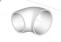
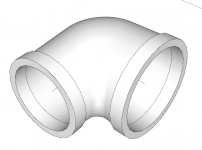
Here is a similar elbow I found online in case I'm not making myself clear -

large.png

(from https://grabcad.com/library/threaded-reducing-elbow-1)

Ignore the end details it is only the body I'm looking at.

Is it possible to draw a reducing elbow in sketchup or should i do battle with fusion 360 again?
 
I don't know the answer I am afraid, but am interested to see you can go from sketch-up to a 3D printer. I have bought my son one for his 18th Birthday at the end of the month (his choice of present but I am itching to have a play too!) - can I ask what printer you have in case I can do the same with sketchup files? I have a Mars Elegoo Pro 2 if that helps.
 
Robert, Just had a quick google and I think the process is to draw the model as a straight funnel with your large and small ends, then bend the model 90 degrees.

You might need a plug-in.

HTH.


[youtubessl]ZyRkPGhSWns[/youtubessl]
 
Must have been searching with the wrong terms as i didn't find that Malc. will look later.

Printer I have is a Creality ender 3 V2.

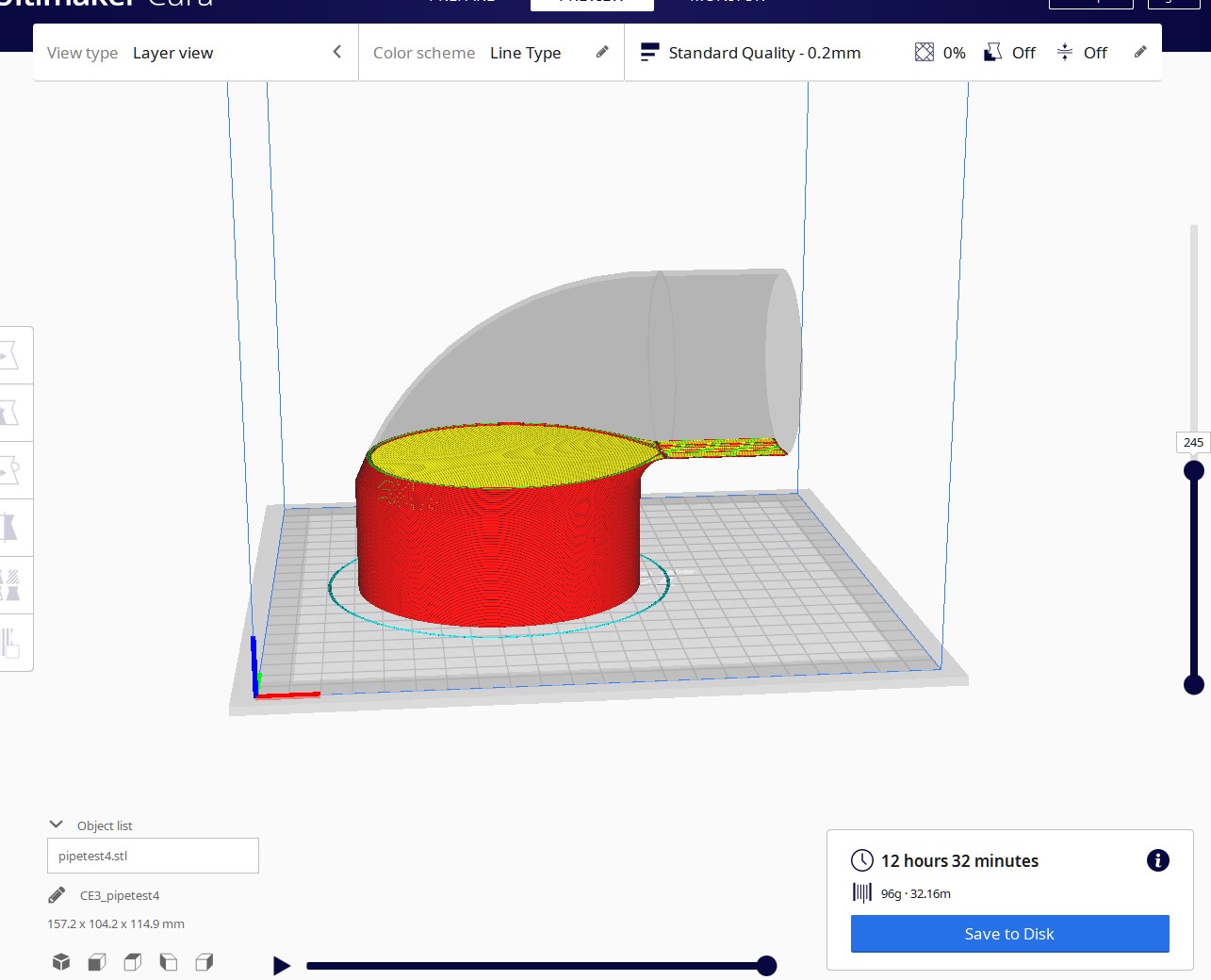
I only put it together the other day and so far only printed a stupid model file that came with it. I drew a test piece in sketchup make 2017 and exported it as a STL file using a STL addon. You then load the file into a slicer (Cura - a free open source download) and let it slice it. That gives you a gcode file you can save and load onto the printer to print. Cura said my test would take 13 hours so I didn't bother printing it as I just wanted to test the process.
 
You've done it again Malc....given me a headache.

That extension works but seems uncontrollable :)

In the video you see the rotation happen then the ends are tidied up as the bending is approximate. If I rotate by 90 degrees according to the dialogue boxes the cone is bent by about 45 degrees from straight. If I guess how much to rotate so that it looks like 90 degrees the ends distort a little. That said it certainly looks the part. Need to work out how to get the ends the right diameters without ugly steps. Maybe tomorrow.

And thanks for finding that, it has helped make progress.
 
StevieB":1cc21ysq said:
Thanks for that Robert, much appreciated.

No problem. you don't need the printer to have a play with the process. Cura supports loads of printers so yours will be there and default settings will be done for you. Make 2017 needs a free add on to export STL files but I think I read the online sketchup has it as an option as is.
 
I coukd tell you how to do it in autocad. No idea in sketchup.

3d printer is on my "when something else doesnt take my bonus" list.

The ender 3pro is the machine im watching so will be good to get your long term review in a couple of months tome.
 
Late to the party but another option:

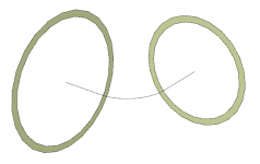
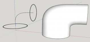
Ends of the elbow without the end details and a centerline.
Screenshot - 8_10_2021 , 11_28_30 AM.png

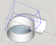
Use Loft along path from Curviloft by Fredo6 to create the inner and outer surfaces.
Screenshot - 8_10_2021 , 11_29_22 AM.png

Push/Pull to add the length for the ends and then Joint Push/Pull.
Screenshot - 8_10_2021 , 11_30_59 AM.png

For 3D printing, I would suggest modeling in meters and then import the .stl into the slicer in millimeters.
 
The printers are good fun, my kids got one each after a course at the local college. I've been using them to print bits and adapters for festoon stuff. I'm using cura to send the files to the printer. There are lots of useful models on thingiverse.
 
Dave's suggestion worked beautifully. I've since realised that I drew it with an outside diameter when it should have been inside so I'll have to do it again. And I think it needs a support or it will try and print in thin air as it turns the corner.
pipetest.jpg


Time to order a roll of filament too as I only have the sample that came with the printer.

Appreciate the help. I'll post some pictures when and if it becomes a real object.
 
Good job Robert.

Not sure if you did the thing I suggested with modeling in meters and opening the resulting .stl in Cura as millmeters (or inches) but that's helpful to allow you to make finer detail. By their nature .stl files are unitless so you can leave the model in meters when you export. Here's an example.

Motor bracket modeled in meters.
Screenshot - 8_11_2021 , 3_35_11 AM.png

Uploaded in inches.
Screenshot - 8_11_2021 , 3_33_42 AM.png
 
Dave R":2lxllcu8 said:
Not sure if you did the thing I suggested with modeling in meters and opening the resulting .stl in Cura as millmeters (or inches) but that's helpful to allow you to make finer detail. By their nature .stl files are unitless so you can leave the model in meters when you export.

I didn't but I still could. Not sure I'm getting the reasoning though.

I thought this was like the scale thing you come across in sketchup sometimes where you draw it 10x bigger and it comes out correct when you scale it down but would have had errors if drawn full size from the off. But there is no scaling here.

So changing sketchup units to meters and drawing this thing the size of a building does what?

Oh and that extension is amazing in what it can transform. I can see me using that again. I used it pretty much by guesswork as i couldn't understand what the prompts were telling me. kept trying to select surfaces to do it all at once then re-read your post saying inside then outside and got there.
 
Robert":vu3rrxue said:
So changing sketchup units to meters and drawing this thing the size of a building does what?

It allows you to model finer detail than if you model at full size because it avoids running into SketchUp's minimums for distances between end points that can result in missing faces which make non-manifold objects.

Another example in which I did that. This is a handle for raising and lowering a drill press table. The fine detail and very smooth curves couldn't be modeled in SketchUp at life size.


Robert":vu3rrxue said:
I thought this was like the scale thing you come across in sketchup sometimes where you draw it 10x bigger and it comes out correct when you scale it down but would have had errors if drawn full size from the off. But there is no scaling here.

It is but there's no need to scale the model down because the .stl file you need to export has no units.


Glad you found Curviloft useful. Play with the other tools it has. I think you'll find them useful, too.
 
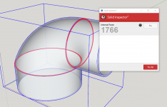
Having a bit of an issue with the models from the curviloft extension.

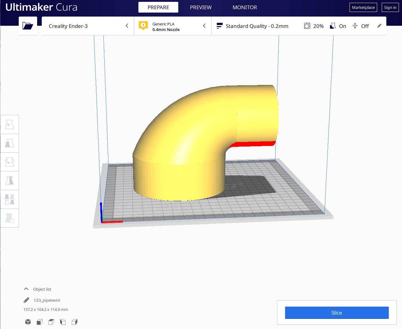
Other things have been taking my attention so I've not got round to printing which is good as I think the model has errors. In sketchup all looks fine. In Cura part of the internal space is solid filled.

I made a 10mm internal radius and let the outside curve take care of itself. The path was a curved line from end centre to end centre with a suitable looking 'bulge'. That 10mm height comes out as solid inside on the model. I have auto infil and auto supports turned off. Above and below that 10mm is hollow.

pipetest2.jpg


I wouldn't try and print 'as is' because it needs support under the smaller pipe. I'm just trying to get a hollow pipe at this stage.

If I use the bending a cone extension Malc found the results are crude but the model in Cura is hollow. I could tidy the ends and add pipes and mess around making them merge but the curviloft version is much more elegant...if I could get it to print hollow.

It's a bit ambitious for a first print but i like a challenge.

Any ideas to make a hollow model really hollow?
 
Is it your SketchUp model that you started with? If so, can you share that? Maybe that's where the fix needs to be applied.
 
Here's one of many. I did one in meters and it looked exactly the same and had the same solid area in Cura.

http://www.argand.co.uk/pixs/TWH2/pipetest4.skp

Just tried it without the straight sections and the fill is the same but I have 'model errors' - but I just deleted the straight parts without checking the model was complete.
 
OK. There are several issues. First,the surfaces you created with Curviloft are still grouped separately from the rest of the geometry. They need to be exploded.
Screenshot - 8_13_2021 , 11_02_59 AM.png
The second issue is that the inside surface is reversed (exposed blue back faces). The face orientation is important here because it tells the printer which side of the surface gets the print media and which side is air. So the surface with the back faces exposed need to be reversed.

Once you explode the groups made by Curviloft you need to also get rid of the internal faces.Screenshot - 8_13_2021 , 11_03_56 AM.png

The internal faces are the result of the process you used to draw the elbow.

To be 3D printable the group or component needs to be considered solid. In simple terms that means the group or component can contain only geometry, no other groups or components, and every edge must be shared by exactly two faces. No more and no less.

If you have internal faces, there must be edges that are shared by three or more faces. You also don't want stray edges or holes in surfaces. The last one is the reason I recommend modeling in meters.

Here's your fixed elbow. I don't remember what version of SketchUp you are using so I saved it as a 2017 file.
 
Many thanks Dave. I'll have to digest that first post explaining where I went wrong as such things are obviously more important with modelling for printing. Thought the internal shade difference was shadow because it is inside :)

Can't get back to it right now but I will later.
 
Had a lot of family things going on so only just got back to this.

Whilst it was tempting to just take your provided model and work from there i needed to understand and correct the errors. I've now managed to make my model printable without errors (i hope).

I can see what you did with that last version and I wouldn't have expected to get cylindrical ends just because the path had straight lines at the ends but You obviously do and it looks a cleaner result.

Think I'm understanding more now but still have some things to work out (though not for this model).

Thanks again Dave for your help.
 
Robert":2wlamilf said:
I can see what you did with that last version and I wouldn't have expected to get cylindrical ends just because the path had straight lines at the ends but You obviously do and it looks a cleaner result.

The path does have straight line segments at the ends but I kept them short of the ends of the elbow. Then after creating the inner and outer surfaces of the elbox and exploding those groups, I used Push/Pull to pull the ends out. This, by the nature of the Push/Pull tool results in the cylindrical ends.

Robert":2wlamilf said:
Think I'm understanding more now but still have some things to work out (though not for this model).

Thanks again Dave for your help.

I'm happy it's been helpful and glad to be of service.
 
Just for completion...

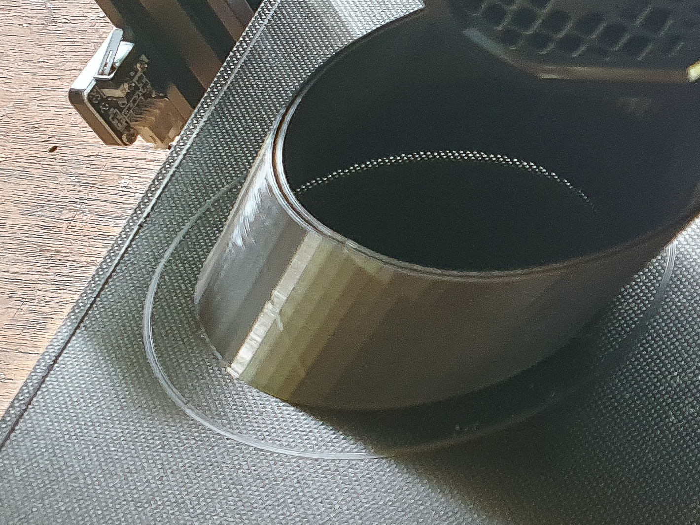
More things learnt. So i drew a model and it was 2mm thick. Wrong. It is 2 skins 2mm apart with a gap between them. This was when i stopped the print as i had two thin shells one inside the other. Blurry pic is all I had before scrapping and going back to Cura.
pipetest-100.jpg


Turned on 20% infil and ran it again.
pipetest-101.jpg


In this one you can make out the zigzag lines joining the skins together.
pipetest-102.jpg


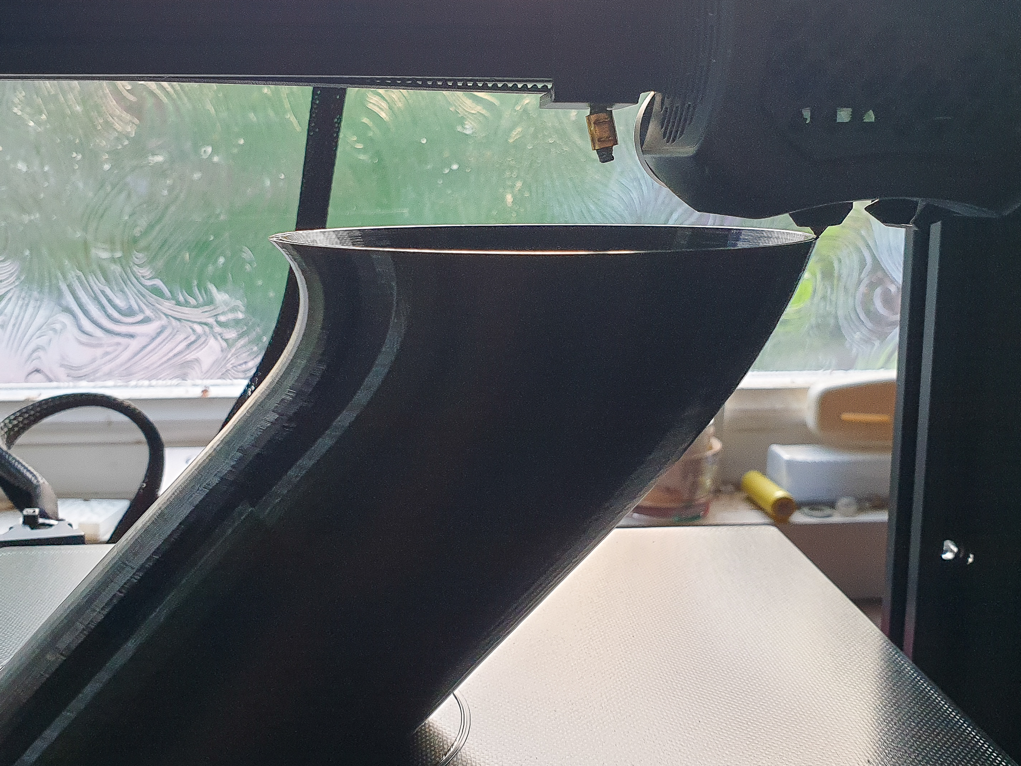
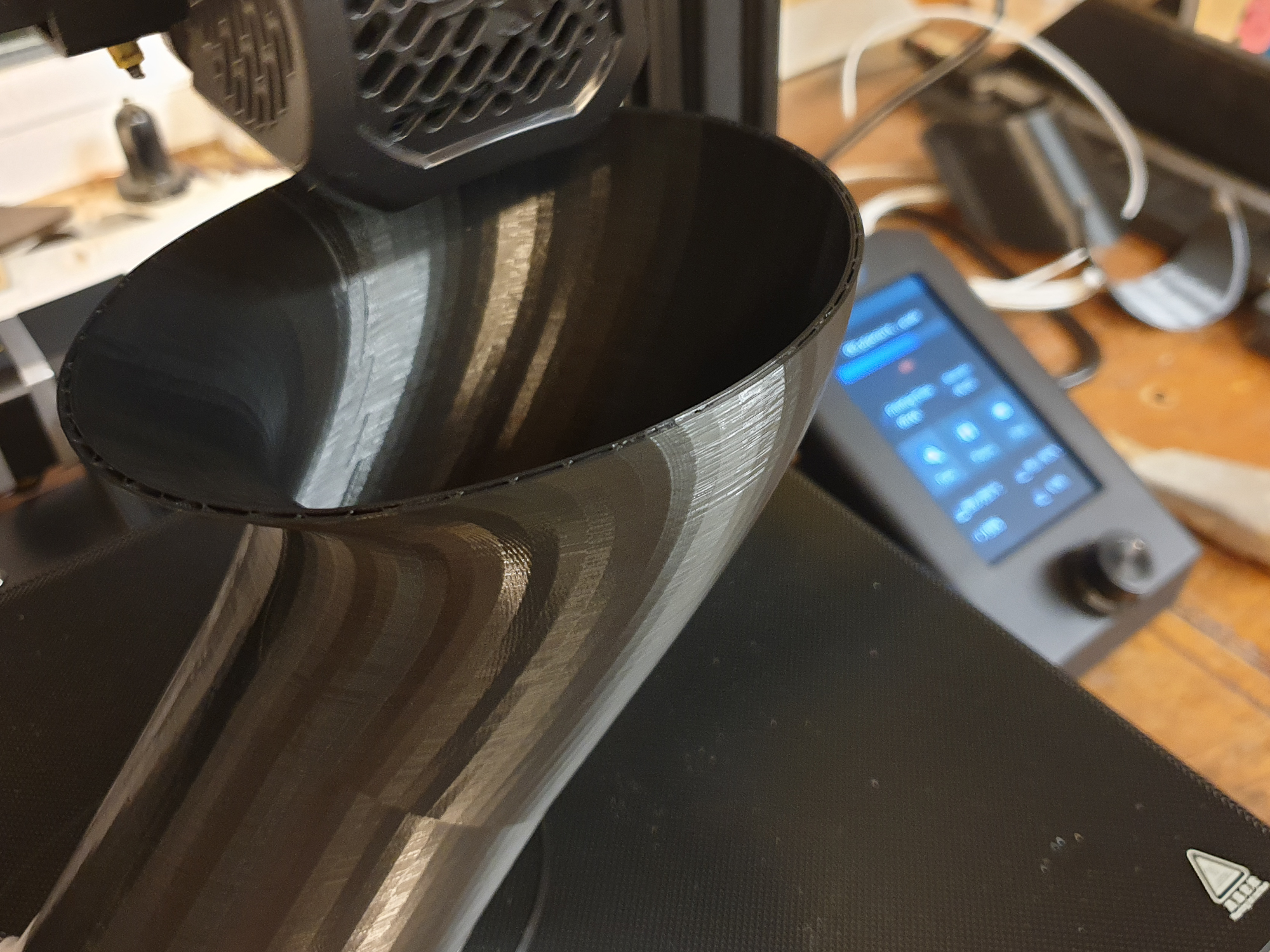
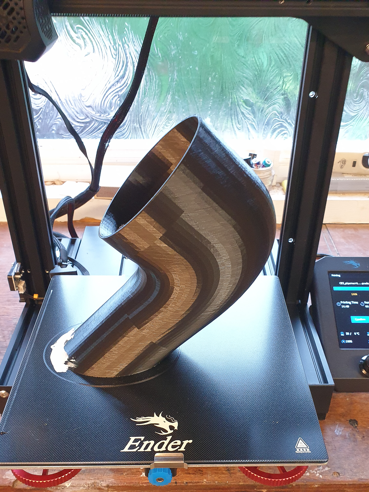
Took around 16 hours so i got up this morning to this.
pipetest-103.jpg


As drawn in previous posts you couldn't print it as the horizontal parts would have to start in thin air and therefore need extensive supports printed under them. I rotated the model 45 degrees and no supports needed.
It does leave me with an angled end to cut off but it seemed the easiest way. Supports added many hours to the print time too.

I got worried about the adhesion to the plate when it was half way done as the zigzag infil shakes the thing a bit. hence the blob of mastic on the bit that will get cut off.
 
Brilliant thread :eusa-clap:

Many thanks to all who have contributed.

Robert...ever thought of offering a service to the forum ? Flat rate £15 per item, say ?
 
great. only issue will be the small end that will be open to the infill and not solid.

everything else, spot on.
 
novocaine":263ilvm3 said:
great. only issue will be the small end that will be open to the infill and not solid.

True but as it is for dust extraction it may just fill with dust :)

...................

I use 68mm drain pipe fittings to connect my hoses for various dust extractions. I even get away with it on the planer/thicknesser as 100 mm hose would mean I couldn't use my home made separator. It will be nice to have custom adaptors on the 100mm ports.

I did test fit it and sizes are perfect.

Thanks all for the help and encouragement.

I bought the printer thinking i might find a use for it. now I'm sure I will. I used to work with CNC metalworking machines and the thing you come to depend on is the reliable accuracy. It might be on a small scale but I've got that easy accuracy again. I foresee plastic router jigs and other things in my future.

Now if only I had space for a CNC router..
 
Very interesting. Hopefully it'll do the job you have in mind for it.

Good job of it, too.

I imagine you'll find all kinds of things to print now.
 
Back
Top