• Hi all and welcome to TheWoodHaven2 brought into the 21st Century, kicking and screaming! We all have Alasdair to thank for the vast bulk of the heavy lifting to get us here, no more so than me because he's taken away a huge burden of responsibility from my shoulders and brought us to this new shiny home, with all your previous content (hopefully) still intact! Please peruse and feed back. There is still plenty to do, like changing the colour scheme, adding the banner graphic, tweaking the odd setting here and there so I have added a new thread in the 'Technical Issues, Bugs and Feature Requests' forum for you to add any issues you find, any missing settings or just anything you'd like to see added/removed from the feature set that Xenforo offers. We will get to everything over the coming weeks so please be patient, but add anything at all to the thread I mention above and we promise to get to them over the next few days/weeks/months. In the meantime, please enjoy!

Bandsaw wheel and motor alignment, and whatever else.

TomTrees

Sapling
Joined
Aug 19, 2014
Messages
390
Reaction score
107
Thought some might find my experiments of interest,
should one stumble across a "bargain".

I've been working on getting my machine running sweetly,
but have still had "fore and aft" issues, and to a smaller extent "flutter" issues.
Now it's not bad blades at fault, just to be clear I've had issues with plenty of types.
The wider 3/4" ones being noticeable, compared to narrow blades.

I've done plenty of stuff on my machine, of possible relevance which I might as well post,
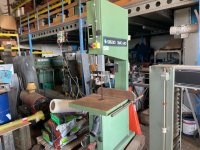
levelling the saw, a 600mm Italian machine, with flat tires, which I've dressed already.

Levelling worth mentioning, in regards to wheel depth and tire edge wear,
and the rest that comes with that.
same with adjustment for differing tire thickness, a third plumbline involved for
both.
(I leave the two permanently on the column, as the floor is damp and I only have
ply pads which get compressed with adjustment.)
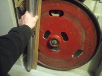
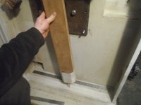
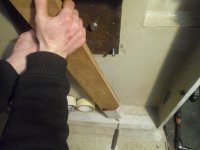
The plumblines have blocks to keep them steady, which could be taped on, as even opening the door is enough to upset plumblines for the next hour.
SAM_4964 (copy).JPG
SAM_4960.JPG
SAM_4977.JPG

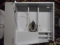
Wheel depth from chassis and lateral position of upper wheel carriage adjustment complete,
Here's a clear shot of the three adjustment bolts for that.
SAM_4749.JPG
SAM_6225.JPG
SAM_4997.JPG

If tires not being in bad state, then onto the interesting bit, which I've gathered should be best done prior, and have documented that stuff in detail.
Wheel alignment, I've also covered to an extent, but which doesn't concern motor alignment.
I'm hoping this will be the fix for this machine, as everything else hasn't been all that noticeable really.
Might as well post a pic of the other work to move on to the interesting bit...

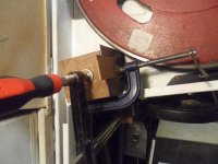
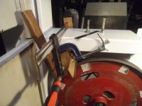
Rebated block to stop slippage, jammed against the lip of the chassis,
tape to stop paintwork damage, ply bit on the clamp head,
ply on the base if not so skookum of clamp used,
A parallel in width plane iron honed at 90, no burr, watch out when assembling your cap iron again as it will score the underside of it.
Wheels hand turned to scrape, that's about it for that.

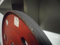
Tires being likely the first thing which is to blame, but turned out it wasn't that much of a difference between just about OK, and properly flat rubber without a hint of crowning,
well, at least not yet anyway.
(The edge profile being speculative and of interest)
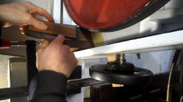
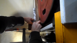
tire dressing jig .png

Screenshot from Dressing bandsaw tires PART 3, truing the upper wheel.mp4 - 1.png

Screenshot from Dressing lower wheel FINAL.MP4 - 1.png

Bit of setting up the wheels, got things better and improved upon sinceBeam & rule .png
SAM_4595.JPG

Which I'll get onto soon.
 
This only came to me recently, and being doing some experimentation how to use it better.
SAM_6751.JPG


This short plank is 1" thick and is barely usable to clear the chassis, but light enough to be used.
FWIW it's 640 long x 92mm wide,
I chose a narrower length previously, and that doesn't allow one to simply traverse across the
width using the spirit level.
SAM_7138.JPG

Note the tightly fitting length of timber is needed here to counteract any tipping of the ali beam,
as it can pivot off the edge of the wheel, so a balance thing,
but also as importantly....
One must be doing this at proper tension, and have blade tracked on both wheels as close to the front without teeth fouling the timber.
Even with that, there is still chance for the wheel to tip back, so one must be applying pressure to the bottom portion of the wheel, (thus the length of timber turns out to be important)
Ps the tiniest bevel might nearly be required, as the plank can get some spelching on the ends, where it can come into contact with the chassis.
SAM_7136.JPG
SAM_7137.JPG

And then onto the bottom wheel, might need rinse and repeat, to make sure the top wheel is
where it wants to be.
(and find masking tape which can actually be drawn on :lol: )
Rightly or wrongly I adjusted only the east/west a smidgen under blade tension, as doing north/south could damage something, well let's just say, I wouldn't be keen on finding that out!.
SAM_7142.JPG
SAM_7152.JPG

Making sure the pulley could be set the correct depth to suit adjustable mounting plate for motor ,
measurement taken, and brought out to the end of the motor shaft.
(a shrink fit on my machine which took a bit of work to set deeper)
SAM_7072.JPG

And for the motor alignment, dropped down to it's lowest point for balance,
and a different pencil, likely used for the same reason but possibly others too, is important if you like a having a the lead on the end of it!.
Visible pencil effective .jpg

Rotating the pulley makes this line easier to draw
Turn,lift&drag.JPG

And watch out that the lead doesn't end up poking out t'other end, which will require another
length of tape due to smudging, or perhaps a bit more troublesome than that if you've got cheap paint, you might score it, which can make retesting troublesome to some extent.

Everything needs be very clean, as the pencil will go haywire over bumps or whatnot.
Pencil mishap.JPG

Hoping it'll run sweetly now, not even inspecting things yet for some speculation or ideas.
Fingers crossed I don't have to delve down the rabbit hole of Peter Sefton's videos
SAM_7078.JPG

And if anything just a bit of bevelling of the top wheel needed, which I only did to a small extent
previously, which may be of interest to some.
SAM_5086.JPG

Getting eager for paint to dry.
Should someone have a damaged or deformed machine, they might find that useful...hopefully.
It's all experimental yet.

All the best.
Tom
 
Well you’ve certainly been busy Tom, but what it’s all about I really am a bit lost I’m afraid, what is flutter btw? Lucky for me my very old Startrite has never needed such shenanigans, a little tilt on the top wheel to centre the blade and all is sweet.
Ian
 
Cabinetman":zcy370qh said:
Well you’ve certainly been busy Tom, but what it’s all about I really am a bit lost I’m afraid, what is flutter btw? Lucky for me my very old Startrite has never needed such shenanigans, a little tilt on the top wheel to centre the blade and all is sweet.
Ian

Most of the work is from the last two years or more Ian.
The machine hasn't being playing nice, whether or not it was a Friday special,
or that it likely had a fall or something dropped onto it, might be the reason.
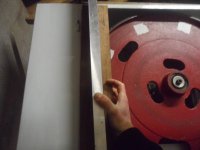
On the table's trunnion, the bolt which threads into lower segment, has a raised bit of casting which were snapped off.

I've tried to bodge things before by crowning the wheels, due to tire damage,
but that lead to my blades getting either set compression, or warpage?
I suspect the former due to the refusal to cut with unused blades.
Lower wheel dressing.jpg


Being a machine with flat tires seems less forgiving than crowned, with teeth running off the edge of the wheels, and how critical a consistent front edge of the rubber is yet to be speculated on. ;)
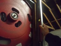
Whilst coupled with large cast iron wheels has IMO less chance of obscuring misalignments.
I've kept all the recent test cuts on some junk to compare,
I was having real trouble, and needed back out and flip to make the cut, so terrible so far.
This machine should cut that stick like butter.

Unless some knowledgable folk like say, Trevanion has better descriptive terms for "flutter", and also "fore and aft", I suppose I'll continue to use em.

Just to make sure we're on the same page,
Flutter, would suggest one couldn't set their side roller/blocks very closely, as it would bounce off both, or imagine it sort of simulating the blade having a wider kerf if you will.

Fore and aft, would suggest the blade wandering forwards and backwards,
in essence, not being great to cut a tenon, i.e having to stop early,
or not being able to set thrust guide(s) close, but not touch the back of the blade.

Seen quite a few posts crop up regarding vibration and whatnot recently, so thought I'd share my
experimental findings regarding alignment.
Seems some are in disagreement regarding lots of things, and just documenting some stuff which could well point out fault.
Hopefully all will be well with the motor aligned now to match the non-adjustable top wheel
(in terms of east/west, that is)
Would be great if it sorts matters out, as it didn't involve much work atall, compared to some stuff
I was working on, wheel bearing spacer damage, and other rabbit holes really.

All the best

Tom
 
Cast iron is able to “move” it may be that the wheels are warped? Not too difficult for an engineering firm to true them up again. Certainly something is remiss to cause the blade movements you describe.
 
Cabinetman":gk27oy9w said:
Cast iron is able to “move” it may be that the wheels are warped? Not too difficult for an engineering firm to true them up again. Certainly something is remiss to cause the blade movements you describe.
I do hope that's not the case Ian, though I think I would have noticed this whilst dressing tires and whatever else.
I did shim the plate 6mm, whatever that equates to in relation the diameter of the wheels,
or should that be the pulley diameter to belt hub?

Here's what it looked like beforehand,
SAM_5279.JPG

so certainly a good enough reason to expect it not to run well.
That stainless turned out to be too thick, so will take a bit of trial and error,
have some other stock which might be more suitable, hopefully right, as I don't wish to use sawplate.
The right shim.jpg

Fingers crossed I don't need purchase a dial indicator.

Tom
 
Maybe you are unlucky.
Like Ian I have a 40 year old Startrite 352 which I maintain regularly but no faffing about and it does everything I ever ask of it within it's limitations.
The only other thing I do when I remember, is run a stone on the back of the blade before setting the guides as in my experience it's very rare you get a perfect blade no matter what the source though some far better than others.
 
When I first got my Record Power bandsaw it didn’t cut well. I made the mistake of reading a book by a bandsaw “expert”. I tried to follow the advice but it was physically impossible to set it up as instructed. I should add that like many others the wheels are crowned on my saw. Luckily I happed to see an Alex Snodgrass video which sorted all my problems with the bandsaw. There seem to be a number of poor design features on many of the cheaper bandsaws and mine was no exception. I have therefore made a few modifications to make it easier to adjust the tension and tracking.
 
Lons":6nyr6lyd said:
Maybe you are unlucky.
Like Ian I have a 40 year old Startrite 352 which I maintain regularly but no faffing about and it does everything I ever ask of it within it's limitations.
The only other thing I do when I remember, is run a stone on the back of the blade before setting the guides as in my experience it's very rare you get a perfect blade no matter what the source though some far better than others.

That could very well be a theoretical concept Lons :lol:
Could I have afforded this machine if it were pristine?

This isn't the only machine I've personally experienced which is troublesome,
a brand new far eastern 20" machine which got sent back, which the rep and the retailer also failed to sort, even with 3 new blades from two different sources...
and another wee one at me folks,
which is only good for curves due to drifting either side of the line whilst using the fence
Both having crowned tires, so it's not just a matter for flat tires.

And regarding limitations with your machine for instance...
Have you compared your machine to something the same or near identical
to it, which had notably impressive results? ...
How do you know otherwise, could it be that you may have a hint of mechanical sympathy...enough to make excuses possibly?

Woodster":6nyr6lyd said:
When I first got my Record Power bandsaw it didn’t cut well. I made the mistake of reading a book by a bandsaw “expert”. I tried to follow the advice but it was physically impossible to set it up as instructed. I should add that like many others the wheels are crowned on my saw. Luckily I happed to see an Alex Snodgrass video which sorted all my problems with the bandsaw. There seem to be a number of poor design features on many of the cheaper bandsaws and mine was no exception. I have therefore made a few modifications to make it easier to adjust the tension and tracking.

I don't anything special from say Snodgrass's viral videos,
It seems to be the exact same rhetoric as with all basic small bandsaw setup videos to me.

The results being the proof whilst using a rip fence, not freehanded or point fence.
For instance here's Graham's machine,
It's only a handful of machines this size what I've seen, being able to resaw any depth at all.
The video is sped up a bit as it's an annoying youtube "shorts" which I disdain,
but even still some notable things like use of the rip fence, thrust guides not squealing, completion of the cut, seemingly without babying the machine too much.

https://youtube.com/shorts/WzJytO-9GOE?feature=share

One could also speculate about those lil ripper's/ the accu-slice (sliding carriage attachments)
on why they seemingly work better than a rip fence, well for the machines exhibited with the jig anyway.
Perhaps these possibly have more mechanical sympathy compared,
but perhaps only for those who don't have their machine setup as it good as it could be?

Time and time again I've came across the same old adage regarding rules of sorts,
For instance having a sharp blade being of most importance, common sense no argument there,
but have you ever seen a machine cut well with a dull one?
Here's a not so sharp, 3TPI regular steel blade being run hard
https://youtu.be/tvhPbNtJISM?t=124

Could pick out a few other channels which demonstrate the performance I should expect from my machine (without editing or music which is nice to see), as before that, I was going by pretty much hear say and gleaning from the odd comment regarding things like beam tension and whatnot from helpful folks at sawmill creek, a frequent online destination for most flat tire bandsaw owners.

Regarding design, it seems my machine is very receptive in regards to doing this mod,
having such adjustment on the pulley, (around 9mm thereabouts)
but perhaps something which shouldn't need doing one might say.

As there's only a few machines out there which have motor adjustability,
I presume its a cost thing, as you don't too many bandsaws with foot mounted motors like the Multico below.
 

Attachments

  • multico b600 motor .jpg
    multico b600 motor .jpg
    153.5 KB · Views: 4,393
TomTrees":2vqmky2p said:
I don't anything special from say Snodgrass's viral videos,
It seems to be the exact same rhetoric as with all basic small bandsaw setup videos to me.

Not sure what you mean by “I don’t anything special”? but the crucial point for me was in blade setup, which contradicts what most manufacturers say in their instructions. From what I’ve seen on forums and social media Alex’s video seems to have helped an awful lot of people.
 
TomTrees":2aic7hhj said:
And regarding limitations with your machine for instance...
Have you compared your machine to somethinThat could very well be a theoretical concept Lons :lol:
Could I have afforded this machine if it were pristine?g the same or near identical
to it, which had notably impressive results? ...

How do you know otherwise, could it be that you may have a hint of mechanical sympathy...enough to make excuses possibly?

Only you can answer that question as I have no idea of the state of your finances, in my case I could afford to buy an expensive high end machine but have absolutely no need

What excuses? There are none to make, my comments come from experience over decades as a hobby woodworker also helped by the fact that I was a branch manager heavily involved in selling machines to small and medium size companies so I experienced issues and capabilities at first hand.
By limitations I mean realistic usage as you would with any machine old or new, clearly while it may handle softwood at maximum cutting depth with ease a a similar bit of hard oak would be more of a struggle.
I have absolutely no hint of mechanical sympathy, the exact opposite is the case, it's a machine to be used and abused with minimal upkeep which is what happens and I cut anything from thin ply to sleepers with varieties of plastic and even the odd bit of non ferrous metals. All I do is keep it clean and lubricated, the guides correctly set and I now only buy blades from Tuffsaws ( other brands are available ;) )

Bandsaws are the simplest of machines, the Startrite being no exception and it's no co-incidence that the older machines retain very high s/h value.

I used to sell machinery many years ago from my branch, unfortunately at the time I couldn't justify a 352 but regret not doing it anyway.
 
You seem to be a hound chasing its tail with this bandsaw Tom, you've been messing with it for years and years now!

Regarding fore and aft movement, did you ever do tests to ensure that all the blades you had were welded straight before jumping to conclusions about the machine? I very rarely get a blade that runs true, I go through a fair few and I would say only one in three or four ever run perfectly. A simple test would be to lay a piece of timber on the bed just in front of the blade, spin the wheels by hand until you figure out where exactly on the blade it moves forward the most, make a mark on the blade where that is happening and then remove the blade carefully without moving the wheels, then turn the blade roughly 180-degrees so that the part with the mark is inside the column of the saw, retension and then turn the blade again doing the same as before with the timber, if the blade rolls forward at the mark again it's the blade, if it's forward more on the opposite side of the blade it's something mechanical.

This is quite often what the 2" blades look like from a reputable company, the truth is it's quite difficult to weld them without warpage or three-folding them could cause a slight bend. A skilled sawdoctor could straighten it out by rolling the front of the blade to stretch it, bringing the back straighter.

pDaXiYp.png
 
I don't anything special from say Snodgrass's viral videos,
It seems to be the exact same rhetoric as with all basic small bandsaw setup videos to me.


Apologies @Woodster for the typo, mean't to be.. I don't see anything special...
Blade setup is a given, can't see why anyone couldn't have just watched the next video down,
which wasn't on an older style delta or whatever.
Not saying the guy isn't a good presenter or anything like that.

Lons":2vpm36qm said:
TomTrees":2vpm36qm said:
And regarding limitations with your machine for instance...
Have you compared your machine to somethinThat could very well be a theoretical concept Lons :lol:
Could I have afforded this machine if it were pristine?g the same or near identical
to it, which had notably impressive results? ...

How do you know otherwise, could it be that you may have a hint of mechanical sympathy...enough to make excuses possibly?

Only you can answer that question as I have no idea of the state of your finances, in my case I could afford to buy an expensive high end machine but have absolutely no need

What excuses? There are none to make, my comments come from experience over decades as a hobby woodworker also helped by the fact that I was a branch manager heavily involved in selling machines to small and medium size companies so I experienced issues and capabilities at first hand.
By limitations I mean realistic usage as you would with any machine old or new, clearly while it may handle softwood at maximum cutting depth with ease a a similar bit of hard oak would be more of a struggle.
I have absolutely no hint of mechanical sympathy, the exact opposite is the case, it's a machine to be used and abused with minimal upkeep which is what happens and I cut anything from thin ply to sleepers with varieties of plastic and even the odd bit of non ferrous metals. All I do is keep it clean and lubricated, the guides correctly set and I now only buy blades from Tuffsaws ( other brands are available ;) )

Bandsaws are the simplest of machines, the Startrite being no exception and it's no co-incidence that the older machines retain very high s/h value.

I used to sell machinery many years ago from my branch, unfortunately at the time I couldn't justify a 352 but regret not doing it anyway.
[/quote]

Presuming you might be fimiliar with the Centauro 600 so.
Some have a lot of differing opinions regarding the setup compared, and to top that off, seemingly
some retailers have published some questionable things regarding the machines,
so you'll have to forgive my assumptions,
as lots have differing ideas of what good performance is.

Startrite Centauro.jpg

Tom
 
Trevanion":ffjxronp said:
You seem to be a hound chasing its tail with this bandsaw Tom, you've been messing with it for years and years now!

Regarding fore and aft movement, did you ever do tests to ensure that all the blades you had were welded straight before jumping to conclusions about the machine? I very rarely get a blade that runs true, I go through a fair few and I would say only one in three or four ever run perfectly. A simple test would be to lay a piece of timber on the bed just in front of the blade, spin the wheels by hand until you figure out where exactly on the blade it moves forward the most, make a mark on the blade where that is happening and then remove the blade carefully without moving the wheels, then turn the blade roughly 180-degrees so that the part with the mark is inside the column of the saw, retension and then turn the blade again doing the same as before with the timber, if the blade rolls forward at the mark again it's the blade, if it's forward more on the opposite side of the blade it's something mechanical.

This is quite often what the 2" blades look like from a reputable company, the truth is it's quite difficult to weld them without warpage or three-folding them could cause a slight bend. A skilled sawdoctor could straighten it out by rolling the front of the blade to stretch it, bringing the back straighter.

pDaXiYp.png

Haha Trevanion, indeed I am much like the dog. :lol:
But I suppose you could call it process of elimination, and figuring out how to do things.

Must try those tests sometime, once the machine is set up that is...

I must say I haven't heard of that test before, that'll be interesting,
have four I can test.
Nothing as obvious as your blade from a glance.

Can that blade be even used?...
If so, then I'd question why the assumption of the blades at fault, since the blades won't cut.

All the best
Tom
 
TomTrees":3aboqcrz said:
Can that blade be even used?...

Yes, but that's about the limit before the machine will start shaking violently when running, there's a lot of inertia in a 2" blade.

TomTrees":3aboqcrz said:
If so, then I'd question why the assumption of the blades at fault, since the blades won't cut.

If the blades won't cut, are the teeth oriented correctly? Sometimes you have to turn a blade inside out to get the teeth the right way around otherwise they won't cut at all. I have to do it every time on the 2" blades as they're intended for WoodMizer-type milling bandsaws which I think they must cut the other way to a conventional bandsaw, so the teeth are facing the wrong way for clockwise rotation and you have to turn it inside out which is quite a challenge by yourself on a wide blade.
 
Trevanion":1v01rnes said:
:eusa-think:
Yes, but that's about the limit before the machine will start shaking violently when running, there's a lot of inertia in a 2" blade.

Thankfully mine look nothing like that, and have had no bothers running without fore and aft, using a narrow tuffsaw blade with 3 welded sections, but my wider blades didn't like the cambered wheels, and damaged many blades before.
Trevanion":1v01rnes said:
If the blades won't cut, are the teeth oriented correctly? Sometimes you have to turn a blade inside out to get the teeth the right way around otherwise they won't cut at all. I have to do it every time on the 2" blades as they're intended for WoodMizer-type milling bandsaws which I think they must cut the other way to a conventional bandsaw, so the teeth are facing the wrong way for clockwise rotation and you have to turn it inside out which is quite a challenge by yourself on a wide blade.
Forgot 2 thank you yesterday for this sage advice, as I was thinking I'd need seek a backwards bandsaw for those blades, phew!
GRIGGIO_SNAC_640_Båndsav___backwarde Bandsaw.jpg


Have you got any speculation regarding getting things right this time round,
or shall I continue to go round in circles :P

Cheers
Ps Here's another old book I've seen mentioned, meant to be a wee bit on bandsaws.
Wondering have you read it?

Tom
0.png
 
I read quite a bit about bandsaws when I first got mine. From this I gathered that most modern bandsaws of modest size are designed to run with crowned wheels. This apparently makes them much easier to set up and cut well, at least with modest size blades. It seems though that some bandsaw wheels are actually crowned and have a flat tyre fitted, whilst some have flat wheels and the tyres should be “dressed” to form a crown. Additionally some urethane tyres come ready “crowned” (for flat wheels) and don’t require dressing. On top of this some older or larger bandsaws have flat wheels and are apparently intended to be used with flat tyres. When buying old equipment I suppose it may not be immediately obvious what type of tyre is needed without having the original manufacturer’s instructions?

The manufacturers of my Bandsaw say not to alter any of the original factory settings for the motor and bottom wheel. The only adjustment, apart from blade tension that is required is to tilt the top wheel using the tracking knob. Given what I’ve read in at least one book, bandsaws with flat wheels and tyres may require more in the way of adjustment to get them to cut well. Good luck with your quest.

Edit: I’ve got a Record Power Bandsaw but I think I’d have been better off getting an older used Startrite! :lol:
 
Woodster":37a92dkr said:
Edit: I’ve got a Record Power Bandsaw but I think I’d have been better off getting an older used Startrite! :lol:

That comment has quite possibly hit the nail on the head right there,
depending on which Startrite you're referring to, if it's the 352 that is...
as in, it poses the question why are those machines held in such high regards..

Yes one can still get parts, and is seemingly a solid machine, although never looked at the
assembly, and likely features a Brook Crompton motor or similar quality, so that stands for those,
but if going for features like near solid cast iron wheels on the modern machines,
seems like it could possibly make up for that, or not, depending on ones opinion. ;)

Some floor standing machines today coming with quite large spec'd motors,
which seem apt for a larger machine,
Take the opposite case, a similarly sized saw to my machine like the SNAC 540, only having a 1.5kW motor compared, which has me curious.

Regarding "better off getting" might depend on ones intentions,
i.e a dependable machine for all manner of light duties...
or on the other hand, performance wise, pushing the limits of it ripping and resawing occasionally that is.

Seems to me many of those opinions of the older Startrites might be compared to dated designs, of say 20 years ago, compared to the Axi's, RP's or other ubiquitous saws with fairly solid cast iron wheels these days.
Would be interesting to see a comparison...

Might it be, that's all possibly be too much in agreement with ye, should the opinion of properly aligned, wheels and motor can make up for tin wheels?

Or is it that folks might be unwilling to find out how accurate older machines were made,
should one have some pristine model which hasn't had some sort of accident in 40 years?

Not sure which, but I don't think I'm far off the mark regards getting my machine to run sweetly.

All the best
Tom
 
There are a lot of ifs and buts in there Tom and unless you've owned an old Startrite 352 perhaps your information comes via google.
I've said my piece and in my case it does everything I want and need so there's not an ounce of inclination to waste time and money pursuing other machines, no sense in that, there are many other more deserving causes that take priority for me.
In your case one can only assume that it's possibly become an obsession, nothing wrong with that btw, we're all entitled to live as we wish and if you get enjoyment trying to perfect a machine that clearly has had many issues from the start I applaud you for your tenacity and dedication. :eusa-clap: I would have lost the will to live many moons ago. :lol:

I'm just off into the workshop to rip down some more reclaimed mahogany, I just switch on the old 352 and it does what I bought it for without complaint unless I'm unlucky and need to change a blade which will cost me an extra 5 minutes. :(

Carry on the good work fella, it makes interesting reading.
Bob
 
We had, I think, five different Startrite Bandsaws where I used to work. Two were used for metal cutting. All of them seemed well made, but I don’t think they had a 352? I particularly liked the largest model they had which had its own blade welding and grinding station on the side. ;)
 
Woodster":2c2hb2bl said:
We had, I think, five different Startrite Bandsaws where I used to work. Two were used for metal cutting. All of them seemed well made, but I don’t think they had a 352? I particularly liked the largest model they had which had its own blade welding and grinding station on the side. ;)

At the time when we stocked and sold them they were probably the most popular brand around and the 352 outsold any other machines we had in the medium sector, they also went into a hell of a lot of schools and colleges, many of those machines are still out there doing what they were made to do.

No one could say they are are technically advanced and certainly far from perfect but built like a brick sh*thouse and very simple which are the strengths of the machines really. It would be interesting to have a crystal ball and see how many modern chiwanese made bandsaws are still around in 30 or 40 years time. :eusa-think:
 
Interesting you said that Bob, mine came from a college art department where it had been used to make frames for silkscreen printing, consequently it was fairly well daubed all over with paint. It cost me £80 and it’s still going very well indeed 25? Years later, as you said it’s all I’ve ever needed.
Ian
 
Cabinetman":3pzxh2ka said:
Interesting you said that Bob, mine came from a college art department where it had been used to make frames for silkscreen printing, consequently it was fairly well daubed all over with paint. It cost me £80 and it’s still going very well indeed 25? Years later, as you said it’s all I’ve ever needed.
Ian
You could make quite a bit of interest on £80 Ian - but what would you replace it with. :eusa-doh:
 
For interest, I bought a pretty poor example of a Startrite 352 a few weeks ago (I paid way too much really but oh well) and I’ve been working on it when I’ve got the time, there will be a thread on it at some point. I’d compare it to a wellington boot, simple, rugged, it just works.
 
Lons":ymoal0ed said:
Cabinetman":ymoal0ed said:
Interesting you said that Bob, mine came from a college art department where it had been used to make frames for silkscreen printing, consequently it was fairly well daubed all over with paint. It cost me £80 and it’s still going very well indeed 25? Years later, as you said it’s all I’ve ever needed.
Ian
You could make quite a bit of interest on £80 Ian - but what would you replace it with. :eusa-doh:

Well I suppose I will then as I shall be selling it along with most of my workshop equipment soon as I transfer to the us. I haven’t looked at prices yet, am I going to be happy chuffed excited or amazed lol.
 
Appologies for the lack of progressiveness regarding an update, I'll edit this later to include pics and likely explain things better whilst I'm at that.

Time for the whatever else part it seems, something you folks might have come across before.

Eventually found a suitable length of timber and planed up accurately, checking clearance (no less than 28mm in my case, this piece is 40mm, which clears the waist section of the chassis,
as the smallest change in north/south will effect this, regardless of upper wheel adjustments.
SAM_7222.JPG

Changed to the use of a shortened papermate biro, as pencils were breaking,
and was cause of much speculation regarding my technique..................
SAM_7225.JPG


This now works really well, and is clearly the way to do things, only an extra layer of ink friendly
masking tape necessary, and removal/thorough cleaning of the cellotape from my ali beam.
Infact it's working so well, that it's highlighted the whatever else :eusa-violin:
SAM_7208.JPG

Not mapped out my wheels yet, but the top one seems to have a problem.

I'm hoping that orientating the possibly bent shaft say 90 degrees, or 180 deg to that might fix things,
but @30mm diameter, I think that's wishful thinking.

Still, I'll be spending a day on all that for the possibility of it being the fix.
Suppose I should hope it be a more involved endeavour than that really.

I reckon you folks might be fairly confident in my setup regarding the rudimentary elements,
so won't need explain elimination of other factors.

What's happening here is
I'm getting two differing lines upon location of wheel, i.e 9 and 3 o'clock.
Seems to be about 5 [ sorry about that b]3[/b]mm(ish) discrepancy between registration of beam on either side of the wheel.
These lines are parallel with each other, which is what has me confused,
should they not meet somewhere in the middle?
Checked again and I couldn't find a spot on the wheel where it might occur.
This is practically un-noticable by eye spinning the wheel, nor with say something rigid like
a block placed against by hand, and as mentioned, not clear when tires dressed either.

As said I've not mapped out anything, just used two points for reference so far,
so perhaps I might find that I can get lines to be anything but parallel,
Since I've already done this test, a rolls worth of times worth of tape, without anything strange like that happening, and not been picking a spot for registration,
I'm fairly sure that's not going to be the case.

Still have to get back to some other stuff on the machine too,
as it needs be documented, so will be interesting to note of improvements,
and whether this variance actually turns out to be problematic under dynamic tests.

Rightly or wrongly I chose what appeared to seemingly be the least discrepancy without going bananas, which turned to be 1.30 on the wheel.

Grinding near two mm from the shim, messy business, that's what I get for joining the dots :lol:
but happy bout that as it likely amounts to a fair bit of tilt factor.
This top line was drawn with the beam on that single position of the wheel, with only a wee bit of rotating it necessary.
I didn't do this with the bottom one, just butted against both sides of the wheel and traversed across the timber.
SAM_7231.JPG
SAM_7234.JPG
SAM_7239.JPG


Also to further delve down some thoughts I've had of the importance of the edge strictly regarding flat tires
in which I was thinking tire damage was the objective to be overcame,
but certainly not to deal with a possibly warped or badly machined wheel.

I just can't get my head around the variance, and why that isn't noticeable without the use of the beam, or say with some other method like Trevanion mentioned.

I do hope the parallel lines doesn't translate to the same amount of rubber which might need be addressed, or both rubber and cast iron :cry:
and why didn't it become noticeable whilst dressing the edge of the tire?
As I may have mentioned I was intending to re-visit the top wheel, as the little I did
seemed to do nothing under dynamic tests (Kelly Mehler's term for under power)
Screenshot from SAM_6242.MP4 - 1.png

Tom
 
I'm thinking of asking my query on OWWM aswell, as I seen at least one wobbly looking welded wheel before which absolutely needed sorting, as that was without seeing it move!

Though I'm guessing seemingly most, if not all of those folks are freehand crowner types...
so I doubt I'd get the answer what would yield the results I'm after.

Perhaps better to post on the Felder owners group, as most flat tired bandsaw users beyond the Creekers might be found there.

Tom
 
Not much to report yet, only got round to inspecting some other stuff, like mapping out the bottom wheel.
Seems from what I've discovered, I've got some thinking to do.

I can see now why I got such misreadings before.
Might have jumped the gun a little with my shim, small beans though.
Took off near 2mm so far.
SAM_7245.JPG

Changed tack a little with the use of the 40mm thick plank,
Finding it's less effort when the plank is butted against the chassis
SAM_7267.JPG

which I needed to trim it a little, so it would fit vertically on the RHS of the upper wheel,
so, a little too short now for checking the motor alignment with, small beans.
SAM_7271.JPG

Rotated the shaft 180 degrees, no change there, speculation eliminated on that part.
Noted the plastic spacer I made, isn't as tight as it once was though.
SAM_7262.JPG

Here's the important bit,
So with a 3mm+ of a variance when beam checked on the left hand side,
(which is totally consistent BTW)
I was expecting to find the same thing with the RHS.

Not so, the line is further back, by about the same amount as the wheel variance.
Now you might get the idea of why my readings were so,
should you imagine registering the beam on the high spot of the wheel, when placed at the RHS,
and not rotating it to check the LHS, the lines would be pretty close,
and combined with the pencil being less forgiving, cost me a lot of tape.

Both these lines were drawn from the high spot, but from either side of the machine.

SAM_7259.JPG

So will be doing a bit more mucking about first, those lines are near parallel to mess about a bit more, will see what the line looks like whilst at the lowest point on the wheel,
It might be the best location to reference off,
and I can test lower wheel alignment on all two or three lines, thinking the likelyhood is
that the two lines would probably be spot on, or very very close,
enough to test, and see how the upper wheel might fair out.

In all likelyhood, I'll be inspecting the bore, but not before everything else.
Seems it might be a tricky one to solve, when I get around to that.
Not holding my breath on being able to be able to spot something obvious.

Cheerio for now
Tom
 
I've done some more testing since, this might be fun. :ugeek:
Mapped out and checked the lower wheel, and found it to be spot on,
no change to the line regardless of where the plank was located, which was pleasing to see.
SAM_7276.JPG

Took some shots of the Axi blade I'm using, though don't think I've ever got a problematic blade before.
Took a bit of fussing to rig up a makeshift table, and it wasn't touched for the photos.
Now I'm not sure how good the blued blade is, on this old carpenters square, if regarding it is as an inspection tool, but good enough for blades I reckon.
The camera picks up everything, so a more honest picture, more like what the naked eye sees below,
SAM_7291.JPG

An adequate blade for testing it seems
SAM_7285.JPG

Even though I've mapped the high spots on the upper wheel, I decided to tram the edge,
just to see if something apparent might show up, perhaps a bit later on.
Whilst pondering about inspecting this wheel off the machine, I reckon this might be of use to know.
No correlation was found between the method to find the high spot earlier, which I was expecting.
Little bit of contact @ 11:49 until 12:20...and a louder scrape @ 2:48 to 3:25
I didn't seek to use a feeler to find the lowest point, but can do again if necessary.
I'm thinking it's not such an accurate way of finding this out, but it was at least consistent.
SAM_7293.JPG

So decided to delve into inspection of the top wheel again.
Things still looking alright regarding my spacer, as the bearing is still proud enabling the wheel retaining washer to capture it
SAM_7297.JPG

The washer could do with swapping around, but that can wait for a bit yet,
as it might likely be problematic with the plumbob when doing further wheel depth tests later on.
SAM_7303.JPG

I crossed out a lot of stuff on the list of variable other methods to test, using the highest spot
on the wheel (the first one.. that is :lol: )
as I didn't cop that the wheel is recessed on the upper section of the chassis,
and I wasn't going to try seeing how variable the casting was, regarding the unworked portion of the wheel.
After seeing how true the lower wheel was, I'm still hoping I can make it tell the truth regarding the upper wheel, fingers crossed!.

A last ditch attempt I've made, which I'm eager to see, no creaking noise during the one single turn I gave it, which is a good sign I suppose, leaving that until later on.
Seems you folks might be getting to know my bandsaw inside and out. :lol:
Daft as you like, but I reckon I could be just lucky.
Doesn't look as bad as I thought either.

Not tried setup yet, but the blade is tracking very far back.
I've gotta few more strips of tape yet to go.
SAM_7314.JPG

With very optimistic anticipation, I'll see ye soon to report back.
All the best
Tom
 
Hello again
Without expecting miracles, I got some time to spend back at the machine,
and whilst tracking the blade, heard that fimiliar thunk again,
so that solves that, not worth flipping the wheel. :lol:

For interests sake, I decided to see what sort of a reading I'd get,
Noting the top wheel needed to be scooted further out, so the edge of the rubber was coplanar.
Didn't think that I gleaned anything from doing so, but looking at the lines of both on the computer,
It seems there is some opposites happening,
which I was thinking might have some importance down the road, should I be able to figure that out, or for someone else to make sense of.
SAM_7338.JPG

Just as not to add confusion, I've peeled off the tape off the back of wheel, and will be referring to things like it was originally.

Seemingly it's a bit feckered, guess I may have loosened things up a bit by swapping the wheel over and manually tracking the blade, as the rear bearing has some noticeable slop now, and ability of the outer race to rotate inside the bore, which wasn't apparent before.


Time for a proper inspection this time
Made up a tool for the circlips. glasses required, and some extra bits needed.!
SAM_7348.JPG

The front bearing was still solid, so perhaps half a chance of some sort'a fix.
SAM_7354.JPG

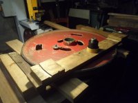
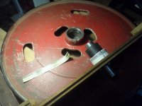
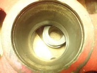
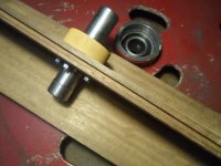
Whilst pondering about finding someone to re-machine the bore and fit a sleeve,
as in this thread...
viewtopic.php?f=23&t=7131&hilit=Centauro

I wonder what the solution was to keep the bearings seated, as surely cutting a groove into the new sleeve might be troublesome, comparing to the Centauro which seems to have a little more meat there.
Remembering a solution for that could be made much like Jack Forsberg's Poitras wheels,
so not impossible to make a sort of cap instead, and welding a washer to the wheel shaft,
as I guess it's not a done thing to machine only one side.
poitras 001 - YouTube.png

If not, then seems worth a bash at another solution I'd been pondering before, but instead
decided to see if a spacer might have been a better idea.
Seemingly I could fit the other two bearings into there,
Turns out I've got two which could be used for the job...
SAM_7355.JPG

Not to mention, the remnants of another, :eusa-think:
SAM_7356.JPG

Seems like that outer race might make a good tool, combined with super fancy 3m stikit abrasive
might get the job done.
Seems I've got nuthfin to loose?
and it possibly might be a more reliable fix for the loose fitting rear bearing if I used the bearing compound.
SAM_7357.JPG

Be nice if that could be a fix, only one way to find out!

Tom
 
Hello again
only getting back at this now as the weathers been good.
After some pondering and procrastination, seems with this contraption like I might, just about... be in with a a shot of bodging this!
(bearing in mind this is optimistic, to say the least.)
Too early to say if it'll work or not though.

Getting some use from my pillar drill
SAM_7372.JPG

Nasty stuff to cut, plenty of oil needed for the dust
SAM_7373.JPG

SAM_7382.JPG

Turned on the lathe with a wooden mandrel thereafter, and cleaned up with remounting on the 30mm bit, as I have only a cheap lathe with no chuck
the pillar drill is more accurate to bring the three surfaces to better tolerance, and should'a drilled the four holes after instead of beforehand...
Just incase I need make another.
SAM_7395.JPG

SAM_7383.JPG


Drilled and transferred graphite on wheel rim..ground a point on some thread for marking.
SAM_7417.JPG

Drilled appropriate sized holes for router bit and wheel retaining bolt
SAM_7424.JPG

Upon testing the jig I noted a tight area, but seemingly not regarding the circumference and possibly just a little area on the inner part of the wheel.
I should note that the front bearing is still tight, I swapped it out for one of the old ones I had.
I don't think I'd be in with a chance with this otherwise.
SAM_7434.JPG

Marked out the bore to see if something might become apparent, not even a hint of something obvious
SAM_7435.JPG

This is a job where your knees are best not in a heap from landscaping.
Very easy to cock the contraption whilst boring to depth, don't lean too heavy.
Turns out the little bit of the plank overhanging makes lovely handles. SAM_7437.JPG
 
Getting past the original spec bore, to get into the wallowed area, means I may need to make another bore insert
SAM_7444.JPG

Cleaned up and full depth, taking nothing off anymore
SAM_7466.JPG

Taking another lick off it with some masking tape, back to boring it to depth again, being even lighter handed than before.
SAM_7471.JPG

Another lick, hoping to get the tool to drop into the bottom without needing to be well worked down into the bore.
Still messing around yet, and likely will have to make another tool.
I've got an outer race which I'm testing the fit with.
SAM_7472.JPG


With a bit more pondering, after forgetting the wheel retaining screw was present underneath and pulling up the bearing through the bore...
I thought it might be likely more helpful for others who don't have the luxury of having one bearing seating well, and perhaps myself also,
if I had a go at possibly improving matters, and seating two more of these old bearings for more surface area ...
and perhaps for interest sake also, having pondered if the races could be used for extra rigidity, though there is 0.4 of some sort of shim needed if so,
as there would be slop in-between the circlips.

Not that I noticed any slop with the single bearing, but that perhaps it might be legitimate a reasonable bodge for others..should this work.
Also thinking I might notice a ridge whilst inserting the shaft, but no hint of anything there.

Took out the bearing to photo
SAM_7476.JPG
You might make out a pair of score lines from pulling the bearing through.
SAM_7474.JPG

Hoping to get witness marks mostly on the bottom/deepest area, as I reckon it might be slightly tapered at this point.
SAM_7480.JPG
SAM_7484.JPG

Needed to use the wheel retaining washer to plunge the tool deeper, (I made a heftier one which wouldn't warp)
and got a bit greedy, tape slips and mushes up, clean and repeat.
This might be a sign that I was removing the deeper area, still unsure really, and I filmed and watched again, still none the wiser.
Likely needs another lick, and possibly some selective removal, but will be cutting the stainless steel shim stock of sorts to see what the fit is like, before proceeding further.

Tom
 
Didn't post a follow up on the rest, as I wanted to give some idea of whether the bore fix
would hold up.
Not gave the machine a good test yet, as I wanted to get stuck into working on the tablesaw.
Regardless of that, the fix proved successful for the interesting part, so I'll get this bit over with.

Bearing in mind, I don't have the funds to splash out on getting an engineer to fix it, :eusa-violin:
and this is not intended as any sort of tute, but a bandwheel boring bodge bonanza. :lol:

I have documented this better on the bandsaw forum for those who like the misery.
Some little changes made for the second bearing journal, mainly removing one of the bearings,
and inserting a shim under the puck.
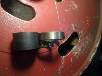
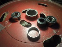
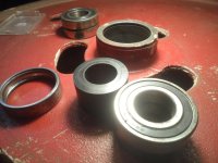
SAM_7944.JPG
And some sleeves made from an old toaster
SAM_7617.JPG

Turned out a pair of old bearings would make great bearing spacers,
a well thought out wheel for sure.
The pair of outer races, to ensure the sleeve doesn't try to escape.
SAM_7669.JPG

Now that's over with, time for the interesting part.
 
Now that the wheel has proven to be solid, time for further inspection.

I mentioned the variable earlier, thereabouts around 4mm.
Here's the picture again for ye's
SAM_7208.JPG

That was because it turned out my upper wheel face had a 0.5mm discrepancy,
the thickness of my Shinwa rule.
The lower wheel had about half this.
SAM_7787.JPG

So using the scribing beam, whilst rotating the wheels, and testing again...
I found my 24" wheels needed to be dressed to around 0.2mm for the 4mm error to disappear,
i.e the pen lands in the same spot.
SAM_7760.JPG

Custom height file handle, though would be much better to choose thicker stock,
so the file cannot be used upside down!..
SAM_7761.JPG

Draw filing is nessecairy to get some sorta bite,
but it does leave ridges, so likely a good idea to switch to a finer file,
or indeed perhaps a diamond hone?
I "tried" other affixed methods, like a second cut files edge,
which had no impact, and likely just followed the humps and valleys, just like a method I tried earlier, which I won't bother showing.
Too lazy to weld up a hefty bracket, and drill an old file to do the job,
though if I'd the space for some lemons, I certainly would.
SAM_7790.JPG

With the wheels now accurate, that alignment were possible,
a true datum line was scribed, and everything aligned.
I did revisit the motor, so might as well show that.

Now aligned on both axis
SAM_7961-01.jpeg

A bearing with a larger ID I had hanging around, done the job nicely,
but any sort of similar shaped thing, what's accurate would do the same.
SAM_7840.JPG

Now that's what you call sure-worthy co-planar adjustment ;)
SAM_7863.JPG

Figured out also, there's no such thing as flat tires,
which was very apparent whilst attempting to cut some green ash using a 3TPI blade,
with no/not much set.
I couldn't get the cut completed until I dressed a crown on the tires,
as per Centauro's spec (crown 1mm closer to the front edge)
and then it were just about possible.
That's mentioned on the SP manual, which I only seen recently

" MAIN TROUBLE AND RELATIVE REMEDIES "


The blade moves very far back when it receives the cutting force
- Insufficient flywheel seal convexity, notify the technical service of the area dealer.

Not to mention mentioned on the ACM promo also.
Those being the two biggest names in the business, so I think that myth is busted. :lol:
p.s there is accounting for the tongue in this picture, (it ain't one piece of timber, the tongue is in-between two timbers in-line)
SAM_8048.JPG

Just seems as such, if not stretched out
SAM_7994.JPG

One could speculate in my ignorance, that a machine aligned just well enough for the blade guides to be set very closely, without contact being good enough for some...
but seemingly what might have a tendency to compress set, if the tires don't have sufficient profile.
As without even cutting anything, and playing by the Italian's rules with a 3/4" blade "teeth off the rubber" ...
On a tire with such a flat profile, will do such a thing?
I've experienced this twice now, with a blade which was cutting plenty of iroko,
and another new one the same.

Once I changed blades, the saw will happily cut now, as one would expect. :eusa-dance:
SAM_8120.JPG

So some food for thought for those who don't have a Centauro CO
or another saw which has a foot mounted adjustable motor, and accurate groove in the wheels!

All the best
Tom
 
I’ve not been able to follow it all Tom but this caught my attention.
"The blade moves far back when it encounters cutting force" — that’s from memory, don’t you have a bearing or similar behind the blade?
 
Cabinetman":mokmyqm6 said:
I’ve not been able to follow it all Tom but this caught my attention.
"The blade moves far back when it encounters cutting force" — that’s from memory, don’t you have a bearing or similar behind the blade?

Indeed I do have a thrust roller guide Ian, and one of the issues I were having, was the blade walking back onto it with barely any pressure atall, effectively slowing down the motor, plus the blade becoming deflected also.
Now I have lots of "beam tension" with the crowned tires, ala something like the Centauro spare tire profile, that I don't need upgrade the thrust guide, nor the side rollers either (all a bit sloppy from having welded a new face onto them)

Might as well post some on that, even though it's kinda a lousy method, and more difficult than
what I've done to crown tires in the past, it might be less irksome for someone who doesn't wish to hone the sides of their plane iron, and doesn't have some better method readily available.

So decided to try using some saw plate for the job, and profiled it accordingly
SAM_8061.JPG


I found this diamond tool nice for final touching,
as it turns out it's not a good idea to have a perfect fit, since that can wipe out the apex
the very thing one is trying to establish!
SAM_8079.JPG

It turned out the block I were using was too narrow, so I glued another bit onto it,
to allow for shimming with duct tape,
so the block is aligned on two axis now, bearing in mind the wheels are actually trustworthy now.

SAM_8083.JPG

SAM_8082-01.jpeg
SAM_8082-02.jpeg

Whilst making sure the wheel is coplanar, of course! :oops:
That cost me some rubber & effort
SAM_8108.JPG

Advancing the cutter is much nicer with some sorta wedging system
I done similar with the upper wheel, but didn't have a blade installed,
so it might not be very advisable to show, as I reckon I might've tipped the upper wheel at some stage.
SAM_8101.JPG

Couldn't say it gives excellent results, as the saw plate is kinda soft for the job.
Thankfully the blade seems happy enough though.
SAM_8105.JPG
SAM_8106.JPG

Tom
 
Back
Top