• Hi all and welcome to TheWoodHaven2 brought into the 21st Century, kicking and screaming! We all have Alasdair to thank for the vast bulk of the heavy lifting to get us here, no more so than me because he's taken away a huge burden of responsibility from my shoulders and brought us to this new shiny home, with all your previous content (hopefully) still intact! Please peruse and feed back. There is still plenty to do, like changing the colour scheme, adding the banner graphic, tweaking the odd setting here and there so I have added a new thread in the 'Technical Issues, Bugs and Feature Requests' forum for you to add any issues you find, any missing settings or just anything you'd like to see added/removed from the feature set that Xenforo offers. We will get to everything over the coming weeks so please be patient, but add anything at all to the thread I mention above and we promise to get to them over the next few days/weeks/months. In the meantime, please enjoy!

Staircase upgrade - ...

RogerS":2xfdhffs said:
If anyone is interested in how you actually go about making the wreath from a drawing then take a look at this guys work. For the 'How to' scroll right down to the bottom.

Pity he is in the USA :(

Which guy...?
 
There's a big jump at the end of that photo sequence. I sort of understand now about making the twisted wreath, with ends at right angles and sides vertical. But how will you get the profile shaped? The Vietnamese workers chose a profile they could make with an angle grinder. The one you want is nicer, but probably harder. From knowledge of old tools, I think the next step would be rebating, probably with short, curved planes, then shaves and carving tools. What do you have in mind?
 
AndyT":138t7lox said:
There's a big jump at the end of that photo sequence. I sort of understand now about making the twisted wreath, with ends at right angles and sides vertical. But how will you get the profile shaped? The Vietnamese workers chose a profile they could make with an angle grinder. The one you want is nicer, but probably harder. From knowledge of old tools, I think the next step would be rebating, probably with short, curved planes, then shaves and carving tools. What do you have in mind?

Rough out as much as possible on the bandsaw. Then maybe a bit more with a sabre-cut in the angle-grinder. Possibly using a smaller sabre-cutter and loan of Lons's gizmo to get even closer. Finish up with gouges, rasps and blood. It won't be easy I know. Almost certainly will be done when fixed in situ.
 
After spending what seems like an eternity (not helped with the shenanigans with a recalcitrant farmer :evil: ) fiddling about with bits of polystyrene, thinking I was getting there but then realising I'd completely forgotten the twist, I'm getting close to the point of admitting defeat. I am finding this so hard to visualise. To visualise 'inside' the raw material as to the line of the finished item.

I finally had the idea of cutting a thinnish lath that I could twist and approximate to the required curve - see below. It's nowhere near perfect but I think gives me some chance of actually doing this.

I know the lines are clunky but that's because I can't bend laterally very easily in the direction I want to go.


Ignore the horizontal cutoff at the top of the upper-flight 'spindle'.

Possibly the upper flight spindle needs moving further up-flight to smooth the curve out a bit.
 
Roger, I would start with the spindles. Mocking up the top of the spindles in situ gives you a series of non-negotiable points. You have no choice but to connect them.
 
Don't give up!

You were getting to grips with the established techniques for drawing the shape you need. I was learning just by following on - I'd never understood that the complicated drawings were of the outside faces of an oblique box enclosing the twisted part. That was a revelation. I'd not even twigged that vertical surfaces will always be vertical and that the shape of the rail is constant, so a cross section at any point will always show the true shape.

Now that you know a lot more than you did, I think you should have another go at applying the time-tested procedure. Ignore the Vietnamese lads winging it with an angle grinder. Follow the good US instructions you showed us.

If this double twisty bit that you have been trying to mock up doesn't feature in the instructions, ignore it for now and do another part which does. Cut it in softwood as a dry run - no apprentice would be expected to get a perfect result first time.

I reckon the experience of making a different curve will turn on some lightbulbs in your head and you will grasp what you are doing with all those arcs and lines on the paper and be ready to tackle the hard stuff as documented in the books.

That staircase needs something better than sections of straight mopstick!

PS - I've read that old stair builders were taught how to make a scale model first, but using the proper drawing method. That might be a good low-risk approach to getting to the point where you can visualise the shapes.
 
I think what I'd do at this point is to go back to the beginning of the tangent method. The initial attempt didn't work out because the lines of the two straight handrails don't intersect so there's no oblique plane to work in. However, you can change that - shape an upward and downward bend on the two ends while keeping the same line in plan, so that the new lines do intersect. Then you can use the tangent layout to shape the wreath.
 
Mike G":h9q2oefk said:
Roger, I would start with the spindles. Mocking up the top of the spindles in situ gives you a series of non-negotiable points. You have no choice but to connect them.


I've already done that, thanks, Mike. I made a couple of extra thick spindles at the right height + handrail and also the right angle on the face to represent the end of the straight handrail.
 
spb":17kfxyx2 said:
I think what I'd do at this point is to go back to the beginning of the tangent method. The initial attempt didn't work out because the lines of the two straight handrails don't intersect so there's no oblique plane to work in. However, you can change that - shape an upward and downward bend on the two ends while keeping the same line in plan, so that the new lines do intersect. Then you can use the tangent layout to shape the wreath.

I like that pragmatic approach, thanks.
 
Looking at your flimsy mockups can I suggest another way to do it?

you can get goosenecks as just rods without lamps or whatever on the end and that gives you a bendable poseable rod. Cut a pile of cardboard bread slices with a middle hole to your handrail section and slide them on every inch or so.

Then you can mount the ends and bend it and rotate the slices as you like.

Not looked very hard but found this on Amazon for £16 https://www.amazon.co.uk/Super-Rod-SRG3 ... 00FXSL8GO/ also CPC have some 450mm ones for £4.50ea https://cpc.farnell.com/pulse/pls00079/ ... dp/ST01639

Just a thought :)
 
OK...outstanding questions...

1) I need to 'fix' the tangents (as Stephen -spb has pointed out). Do I fully understand what this means or how to do it ? Not at the moment.

2) I'm confused about the two terms 'face mold' and 'falling mould'. "Custom Handrails' refers to both. But I can find no reference in the '101 Guide to tangent handrail drawing' ( shown here to the falling mold.
And as this is my 'bible' for doing the drawing, I can't see how or where I get the falling mold from.

I'm still leaning towards the Eastern approach and also Roberts suggestion.
 
I've only watched a couple of videos out of curiosity. I didn't understand 'mold' either but in my mind I changed that to 'template' as in something that gives the cutting lines in one plane (or call it view or elevation).... and that seemed to make more sense. I could well be wrong of course :)

Other thought... couldn't you practice this stuff at say 1/4 scale or smaller with some scraps? Maybe just a square section.
 
Robert":2epig8bl said:
I've only watched a couple of videos out of curiosity. I didn't understand 'mold' either but in my mind I changed that to 'template' as in something that gives the cutting lines in one plane (or call it view or elevation).... and that seemed to make more sense. I could well be wrong of course :)

That's where i'd got to but which one is in plan view and which one is the side view? Face to me suggests looking at it from a horizontal direction but I think that that might be the falling mould.

Regardless as to which is which, I can find nowhere to see creating them both.
 
And to further mystify things, di Cristina makes no reference to "falling mold" !
 
This isn't an area I have studied or tried, but from skim reading of old books I do know that there were several, different approaches. The originators of each claimed theirs was the best. Stir in a century or so, add UK/US terminology diversion and the result is confusion.

I think you need to follow just one source of guidance, ignore the rest, at least until you have tried it.
 
Well, just had another look at di Cristina and George Ellis and am none the wiser. I cannot see where or how to create that second mold that Custom Handrailing applies to his blank. So I'm abandoning tangent hand-railing. Not enough information available that I can find and/or understand.
 
spb":1w9mfuml said:
.....However, you can change that - shape an upward and downward bend on the two ends while keeping the same line in plan, so that the new lines do intersect. Then you can use the tangent layout to shape the wreath.

The slope given by these bends will become the two new pitch lines, yes ?
 
RogerS":27q216q9 said:
OK...outstanding questions...

2) I'm confused about the two terms 'face mold' and 'falling mould'. "Custom Handrails' refers to both. But I can find no reference in the '101 Guide to tangent handrail drawing' ( shown here to the falling mold.
And as this is my 'bible' for doing the drawing, I can't see how or where I get the falling mold from.

Acting purely as a librarian here, this might help, from the Woodworker Dictionary:

falling_mould.jpg
 
Thanks Andy. That makes sense. We're till no closer to understanding how the falling mold is created !

As far as the twist is concerned, the bevel line does provide that information.


The green is the overall outline of the blank needed and the inside rectangle is the overall dimensions of our handrail. You transfer that bevel line from the drawing to the end of your blank. And so at one end it will lean to the left and at the other end to the right. Draw up the corners of the actual handrail along the length of the handrail and there's your required amount of twist.
 
Stephen, I understand you correctly then this is the issue why my drawing didn't work. I've extended the two pitch lines of the two handrails and as you correctly pointed out they are not in the same plane and so the tangents will never meet.


Let us assume that the height difference is 115mm (NB arrow should be shown extended to the top of the upper pitch line piece) then, if I follow you correctly, this is the amount that the combined drop on the curve down on the top handrail and curve up on the lower handrail should be. Trouble is, I think, dropping the curve on the top handrail will take it below the permitted 900mm.


Also to drop by, say, 55mm is going to be a steep drop within that tight curve (again...you spotted that !) and one hasn't even thought about turning at this point.
 
How much can you drop the top case handrail by, and extend the lower case spindles by to stay within requirements, get you to where you need to be and still feel right in the hand, or is that not possible?
 
RogerS":2sjy00sn said:
spb":2sjy00sn said:
.....However, you can change that - shape an upward and downward bend on the two ends while keeping the same line in plan, so that the new lines do intersect. Then you can use the tangent layout to shape the wreath.

The slope given by these bends will become the two new pitch lines, yes ?
Yes.

Now, I've never attempted to do this before, so I'm looking at this purely as a geometry problem, but in order for the oblique plane for the wreath to sit in to exist, what the pitch lines actually are is two lines which run between the ends of the wreath and a notional intersection point.

For aesthetic purposes that point needs to be, in plan view, where the two straight sections would cross, and in height should probably be chosen so that the two pitch angles are as close as possible - in most cases, half way between the two joins. For practical purposes it's easier if it can be arranged so that the pitch lines are at the same angle as the straight sections they need to join, but as we're discovering here that's not always possible. In fact thinking about it more the more I suspect it will rarely be except on the widest of sweeping curves; an inside curve such as you're doing will always need to be steeper than the straight section, and an outside curve will be shallower.

I think what I'm getting at here is:
  1. In plan view, identify your intersection point. This is just where the centre lines of your two straight sections would cross if extended, and is point V in the instructions linked from the other thread.
  2. Still in plan view, choose the end points of your wreath where it'll join the straight sections. These should be equal distances from the intersection point. These are A and B
  3. Identify the height of the intersection point. This wants to be chosen such that the pitch lines on either side have the same slope; since VA and VB are the same length, this will be half the height difference between them. This is where V0 will be.
  4. Now you've got the horizontal and vertical dimensions that will define your pitch lines. Your pitch angle is then arctan(height / base), and you can construct the tangent drawings from that.

Then it's a question of cutting the ends of your straight sections at an angle to meet the wreath and fairing the join by eye.

I realise I might be slightly contradicting some of my earlier posts here; I'm following the same journey as you of figuring it out as we go along. It all definitely needs to be mocked up in something cheap first, if only to discover the next missing piece of information.
 
RogerS":3bxj568a said:
Let us assume that the height difference is 115mm (NB arrow should be shown extended to the top of the upper pitch line piece) then, if I follow you correctly, this is the amount that the combined drop on the curve down on the top handrail and curve up on the lower handrail should be. Trouble is, I think, dropping the curve on the top handrail will take it below the permitted 900mm.
Not quite - the idea of the curved up/down sections is to change the pitch angle going into the wreath to make it line up, not to take up the height difference in those sections. The wreath would be spanning the height difference; you'd just be using the curves to smooth the join.

See my previous post (which crossed over with yours) for a bit more detail there; essentially if you use those extra curved sections it'd just be for fairing purposes; you'd be trading off more pieces of wood for a smoother entry and exit to the wreath. If it's helpful I can try to knock up an illustration of the two options I'm talking about with my minimal Sketchup ability later on.
 
spb":ywpj6pv2 said:
.......
I think what I'm getting at here is:
  1. In plan view, identify your intersection point. This is just where the centre lines of your two straight sections would cross if extended, and is point V in the instructions linked from the other thread.
  2. Still in plan view, choose the end points of your wreath where it'll join the straight sections. I assume we measure length to the centre point of the straight section ? These should be equal distances from the intersection point. These are A and B
  3. Identify the height of the intersection point. I assume that this is a 'virtual' position since the centre lines don't actually meet in the vertical plane as discussed previously ?This wants to be chosen such that the pitch lines on either side have the same slope; again, using the centre of the straight section as the reference point ?since VA and VB are the same length, this will be half the height difference between them. This is where V0 will be.
  4. Now you've got the horizontal and vertical dimensions that will define your pitch lines. Your pitch angle is then arctan(height / base), and you can construct the tangent drawings from that.
Stephen...I've put a few points of clarification/question above.
 
Contradicting my own suggestion and looking in a different book, I think you need to add an "easement."

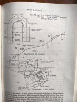
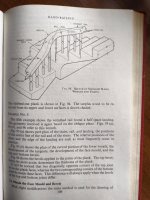
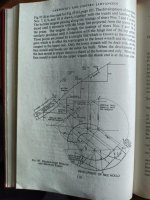
Here's a quick snap of an example from "Carpentry and Joinery (Advanced)" which shows what I think is a similar case. It gets an extra bit of rail at a steeper slope so the two runs connect.

easing1.jpg

I need to go out now but can scan the rest later if it might help.
 
No, that's helpful, Andy thanks. I wonder what 'well lines' are ?
 
Ok, the rain is lashing down here so I have a few minutes more time. The case in question, which relates to stone stairs, does have a landing like yours which might be the source of your problem. (Though the creative spirits who built yours have a few questions to answer too, I suspect...)

It's from one of those annoying books where the diagrams aren't on the same page as the text, so some of them are tacked on at the end.

easement01.jpg

easement02.jpg

easement03.jpg

easementfig95.jpg

easementfig96-7.jpg
 
RogerS":34klo4l0 said:
[*]Still in plan view, choose the end points of your wreath where it'll join the straight sections. I assume we measure length to the centre point of the straight section ? These should be equal distances from the intersection point. These are A and B
Good question - I imagine centre or top would work provided you're consistent throughout. I'd go back and look at the instructions from earlier to see which method they use, and stick with it.

[*]Identify the height of the intersection point. I assume that this is a 'virtual' position since the centre lines don't actually meet in the vertical plane as discussed previously ?This wants to be chosen such that the pitch lines on either side have the same slope; again, using the centre of the straight section as the reference point ?since VA and VB are the same length, this will be half the height difference between them. This is where V0 will be.

What you're doing in this step and the next is basically making up a new set of centre lines that do meet, and also meet the straight sections, then joining them into the straight sections. As you come down the rail, you'll have the straight section, then a downward bend into the start of the wreath, then turn the corner more steeply, then an upward bend into the lower section.

Andy's illustration shows this better than I could draw - the bottom of the wreath doesn't meet the straight section, and doesn't attempt to end at the same pitch. The easing piece smooths the join between them. The pitch line and end point that you'd use for layout out the wreath are those from the top end of the easing piece, and you can choose those to be whatever you want within reason.

Now, where things get more complicated is that in that illustration, since there's only one easing piece, the wreath has a different pitch for the top section than the bottom, and the instructions we've seen for the layout drawings assume that the pitch angle is the same at both ends. My previous suggestion to account for this was to put easing pieces on both sides. Based on Andy's references it seems the more traditional way is to lay it out with different angles, which will be more difficult to achieve but more elegant in the end result. I'm fairly confident I could work out the modified layout process given enough time and paper, but it wouldn't be today.
 
What you write makes all the sense in the world. However if you think about how to get there, it seems to me that it has to be done in several drawings because your explanation involves several different oblique planes at differing angles, surely ?

I've just finished the drawing but struggling to get SU to print out 1:1. Started a separate thread if you'd like to chip in :D
 
RogerS":28qpse8q said:
What you write makes all the sense in the world. However if you think about how to get there, it seems to me that it has to be done in several drawings because your explanation involves several different oblique planes at differing angles, surely ?
Almost - you've got, potentially, three curved pieces in play: the wreath, and two easing pieces. The wreath is in an oblique plane, but the two easing pieces are each in a vertical plane and only need to curve in the vertical direction. While they may warrant their own drawings, they don't need the complexity of the tangent layout.
 
Well, just finished a single tangent drawing. The curve looks better I think. I'll see tomorrow how it shapes up. If NBG then I'll go down the easing/wreath route.

Cheers Andy and Stephen...I think you may have got me on the right track. :eusa-clap:
 
This is a really good thread. Learning a lot here. I hope you manage to make it all work Roger. You have much more patience than me with what is clearly a very tricky challenge having never done it before.

Kind regards, Adrian
 
Back
Top